Here’s one we did earlier!
This project is a realisation of the principles set forth in a whitepaper (written by our Nigel Scott).
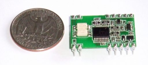
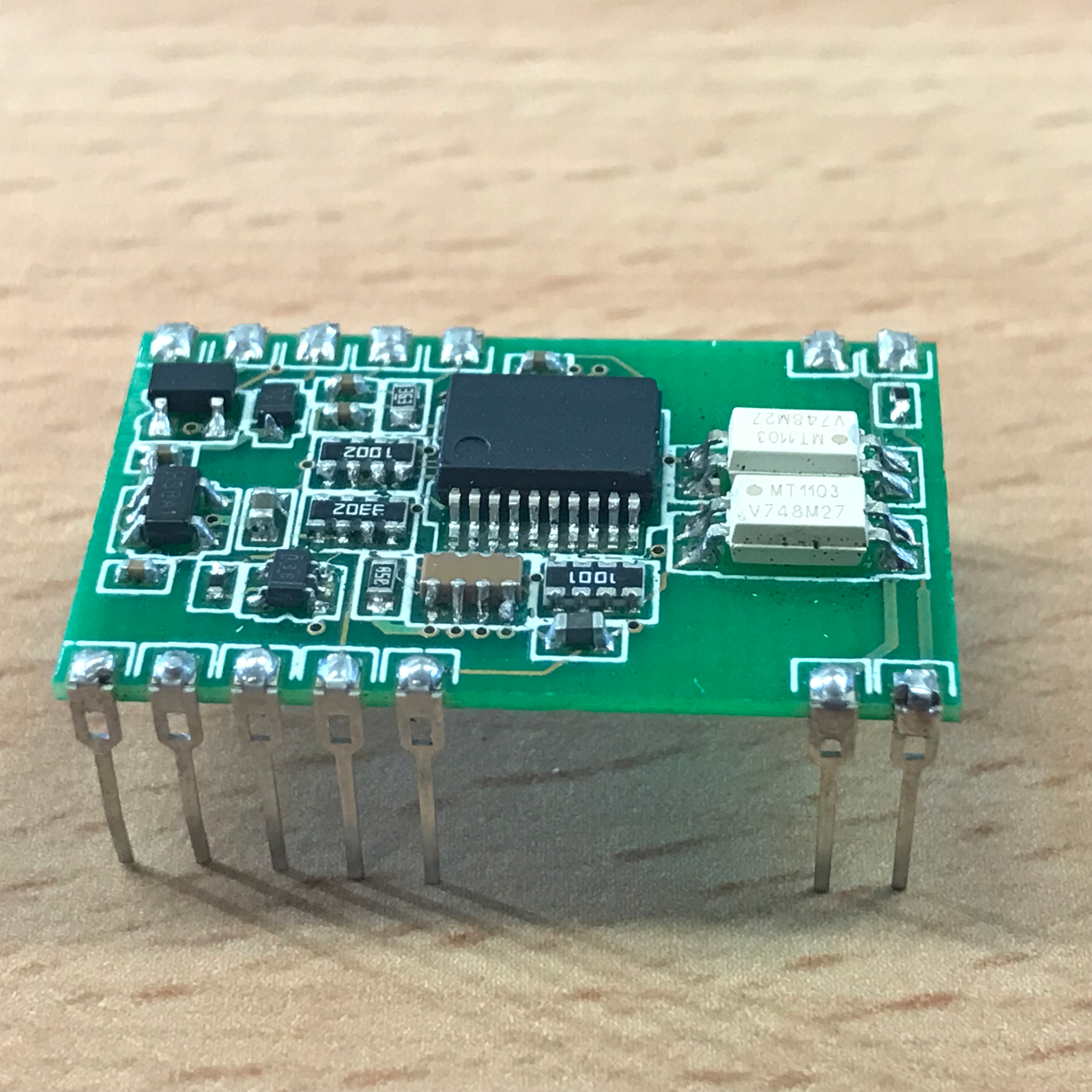
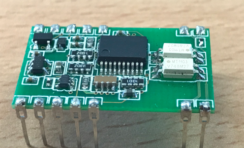
This battery monitoring hybrid system on chip (standard 24 DIP IC package) was designed for a leading battery monitoring company in the United States of America. Once overmoulded it can be PCB mounted in any number of channels, or plugged into a suitably designed battery cell or bloc. The system measures voltage, temperature and resistance (with a small external component) from 1 volt up to 24 volts. Each channel is completely separate and is isolated up to 1000V; communications are via serial link.
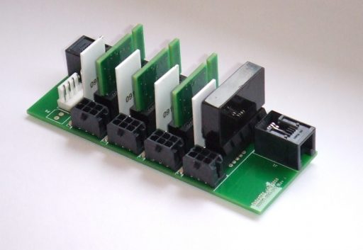
Some standby battery systems are housed in cubicles and there can be many per shelf; these batteries are necessarily compact in form factor and therefore there is little space for a monitoring system. The quad circuit below is the same circuit as the hybrid system on chip, but redesigned for edge mounting to save board space. The simple base PCB is only about 3.5” x 1”, and contains two RJ12 ‘daisy chain’ serial communications with 4 voltage and temperature measurement channels. The temperature sensor, connected by cable via the 6-way battery connections, can be mounted on the monitored cells, or on the negative terminal post as desired. In this format, the PCB can be enclosed in a purpose made enclosure or even mounted in plastic trunking.
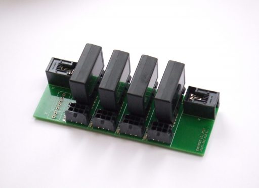
This system can be very flexible; the base PCB could be designed for as many channels as required. 6 x 4, for example, gives a very compact 24 channel module. The communications ‘daisy chain’ will support up to 240 modules, and although each hybrid is designed to measure voltage and temperature, the addition of one component per channel allows measurement of individual cell resistance as well. Once again the design saves on PCB space, as in the picture (below).
The format can have individual encased modules or bare PCBs. A cost saving design could be 8 channels of measurement, enclosed in a single case, together with a single load spanning all 8 channels. This load could be used for resistance testing. The system on chip design could be integrated into a battery or cell lid to create a true intelligent battery. It would be capable of reporting on the battery condition to a system monitor, a PC, or (with a small system comms module) a hand-held device.
If this article is of interest to you – and you want to read more about battery monitoring – please check out our products or read some of our articles & whitepapers.