Although noise & ripple currents occur in many (stationary) standby battery systems, there is a certain amount of controversy about their effects on lead-acid cells; some believe it has virtually no effect and some claim it shortens the service life of the battery. It can be shown however that even where the ripple current is very low, the cell can be affected and the service life reduced.
The effect ripple has on the battery depends on the size and frequency; if the frequency is high, over 5kHz for example, and the battery voltage response cannot follow the ripple current i.e., there is little or no ripple voltage visible to a measuring device, then it would seem there is little deleterious effect. On the other hand, lower frequency currents produce oscillations in the cell voltages and this can be shown to be damaging to the cells.
Noise and ripple sources
Switching noise
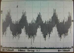
Charger, UPS and load switching frequencies are the main causes of system spikes (positive-going micro excursions) & glitches (negative-going micro excursions). These excursions are micro in terms of time, but not current; the current may be many times the cell or battery float current, but will contain little energy if they exist for only a microsecond. If one of the above system components is not of optimum design, perhaps for commercial reasons, or if the filters are missing, or some components are exhausted (electrolytic capacitors have a finite life, especially in the presence of high noise & ripple currents), then the noise can be significant. In the graph in figure 1 the switching noise is severe and appears as a series of switching current spikes & glitches through the battery.
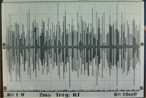
The spikes in the above oscilloscope picture (Fig 1) were due to damaged DC link filter capacitors in the UPS; although they look bad, the frequency is high and the spikes contain very little energy, and won’t cause the battery to respond. Consequently the battery will suffer no great harm from these excursions from the DC float current.
Charger ripple
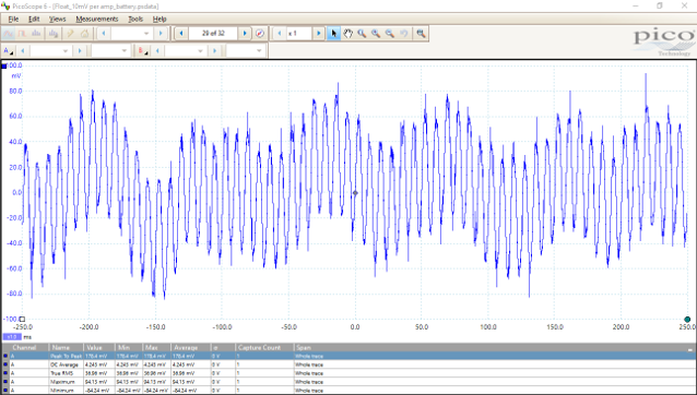
A poorly designed or faulty UPS can cause ripple currents through a battery by taking ‘bites’ of current from the DC link. One of the prime sources of ripple in a battery system is the charger, and is normally caused by legacy designs having a poor or missing filter, particularly in linear systems (fig 2). If the ripple is 60 or 120Hz (50 or 100Hz in Europe) then it’s likely to be the charger. Unfortunately these frequencies are low enough to elicit a response from the battery in the shape of ripple current, and that can shorten the life of the battery significantly.
If ripple voltage can be seen across the battery (fig 3), or a single cell, using an instrument such as an oscilloscope, then it means that the noise and ripple currents are high enough, and the frequency is low enough, to cause the cell voltage to respond. If the cell is responding then that means it is possible that long term damage is being caused. Tests have shown that while responses to ripple current frequencies above 1000 Hz are almost all due to double layer capacitance and not significantly detrimental to battery health, frequencies below 1000Hz can cause the electrochemical processes to cycle1Analysis of battery current microcycles in autonomous renewable energy systems; A J Ruddell, Dirk Uwe Sauer, et al, and changes to take place in the plate-electrolyte interface.
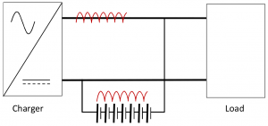
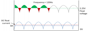
Ripple current is superimposed on the float current of a cell such that a portion of the current is above the float current and a portion below, causing a current reversal (figure 4). Depending on the amount of ripple current present, the portion above (green area) will (over) charge the cell, but the portion below (red area) will cause the cell to discharge (‘micro-cycling’).
In standby batteries a small float charge is applied on top of full charge for the entire service life of the battery, to counteract internal discharge and maintain the battery at full capacity. However if the ripple, which can be large (tens of amps), is overwhelming the float charge, which is by definition small (tenths or hundredths of an amp), the battery can be adversely affected by heating due to AC ripple current.
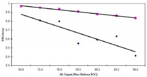
Charge efficiency: Although it appears that the discharge portion of the waveform (in red) is the lesser of the two parts2J.W. Stevens, G.P. Corey, A study of lead lead–acid battery efficiency near top-of-charge charge and the impact on PV system syste design, in: proceedings of the 25th IEEE Photovoltaic Specialists Conference, Boston, USA, May 1996, pp. 1485–1488., the charging and discharging of the battery is balanced, but, due to the charge efficiency of the cell being as low as 40% in the region of 100% capacity2J.W. Stevens, G.P. Corey, A study of lead lead–acid battery efficiency near top-of-charge charge and the impact on PV system syste design, in: proceedings of the 25th IEEE Photovoltaic Specialists Conference, Boston, USA, May 1996, pp. 1485–1488., even a balanced ripple is likely to cause a long-term walk-down in the state of health/state of charge. In tests, large amounts of low frequency ripple have been shown to reduce the state of charge/state of health of a battery from 100% to as low as 70%3A.I. Harrison. Batteries and ac phenomena in UPS systems, INTELEC89, in: Proceedings of the 11th International Telecommunications Energy Conference, Florence, Italy, October 1989..
It is known that, while charge current oscillations which reverse the current lower than 0.05 X C20 are unlikely to greatly affect the battery [1,2], (in a 300A/h battery this would be: 300/20 = 15, 15X 0.05 = 0.75A), current reversal above this figure is likely to reduce the life of the battery, and the reduction in life is dependent on the size of the current fluctuations. According to Koenig4F. König, Der Einfluß von Wechselstrom auf Bleibatterien (The influence of alternating current on lead batteries), ETZ-B ETZ 16 (18) (1964) 536. low frequency ripple can also have the effect of accelerating the metal corrosion. Additionally, micro-cycling will raise the cell temperature, and can cause local changes in the plate-electrolyte interface to bring about electrolyte stratification.
Example: Some charger manufacturers offer their chargers with and without DC bus filters. If the models without filters are used to maintain a float charge on a battery, with significantly less than the designed DC load, the ripple current is likely to seriously affect the battery’s service life. In such a case, depending on the charger specification, there can be as much as 15 amps peak to peak flowing through the battery, when the battery float charge would normally be taking a DC float charge of 0.5 to 1.5 milliamps per ampere hour of the battery (dependent on its construction and state of health). In a 300 A/h battery, for example, this could be less than 200 milliamps. Needless to say a ripple of +/- 15 Amps is not optimum in this situation and is likely to lead to early deterioration and a shortened battery service life.
Ripple & temperature
An optimum operating temperature is an important factor in the service life of the battery. While a small DC float current will, barring other influences, have little effect on battery temperature, large ripple currents can and do affect the battery temperature significantly.
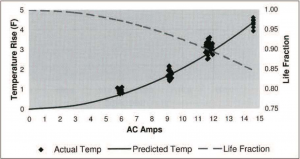
Temperature variations from the manufacturer’s recommendations are not good for standby batteries, as shown in Figure 6, where it can be seen that 15 Amps of ripple can cause a 5ºF rise in temperature, which in turn can reduce battery life by 15%. The recommended temperature for battery systems is 77ºF (25ºC). A rise of18 ºF (10ºC) above this can halve the service life of the battery (Source: Enersys, Hawker, C&D)
‘Micro’-effects
Battery Gassing: VRLA batteries can begin to gas at voltages over 2.3 Volts Per Cell (VPC). Although positive-going ripple is present in very short periods (8ms in the US, 10ms RoW), it can, over time, cause electrolyte dry-out and/or loss of positive plate material 5C&D Technologies: Charger Output AC Ripple Voltage and the effect on VRLA batteries. Technical bulletin 41-2131.
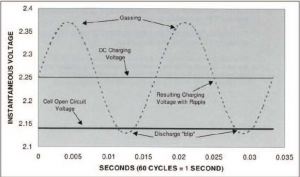
The opposite is true if the negative-going part of the ripple cycle ‘dips’ below the open circuit voltage of the cell. This can cause micro-cycling, rapidly aging the active plate material and the cell can rapidly deteriorate 5C&D Technologies: Charger Output AC Ripple Voltage and the effect on VRLA batteries. Technical bulletin 41-2131.
In conclusion
The effects caused by significant ripple are, over time, likely to cause the battery to deteriorate more quickly than if the DC float current is quiescent. The reversal of current much greater than the float current can cause heating, plate corrosion and ‘walk-down’ in state of health/state of charge, in addition to electrolyte stratification. It is therefore sensible to ensure the ripple current through the battery is as low as possible.
C&D Technologies recommend that a maximum ripple of 1.5% of the voltage be allowed during the bulk phase of the charging, and a maximum of 0.5% voltage ripple during the float phase.
Thus a ripple voltage of a maximum of 0.5% or less of the supply (battery float) voltage should be acceptable 5C&D Technologies: Charger Output AC Ripple Voltage and the effect on VRLA batteries. Technical bulletin 41-2131, to allow minimum early deterioration of the battery. This, in a cell with a float voltage of 2.25 would be 11.5 millivolts 5C&D Technologies: Charger Output AC Ripple Voltage and the effect on VRLA batteries. Technical bulletin 41-2131.
- 1Analysis of battery current microcycles in autonomous renewable energy systems; A J Ruddell, Dirk Uwe Sauer, et al
- 2J.W. Stevens, G.P. Corey, A study of lead lead–acid battery efficiency near top-of-charge charge and the impact on PV system syste design, in: proceedings of the 25th IEEE Photovoltaic Specialists Conference, Boston, USA, May 1996, pp. 1485–1488.
- 3A.I. Harrison. Batteries and ac phenomena in UPS systems, INTELEC89, in: Proceedings of the 11th International Telecommunications Energy Conference, Florence, Italy, October 1989.
- 4F. König, Der Einfluß von Wechselstrom auf Bleibatterien (The influence of alternating current on lead batteries), ETZ-B ETZ 16 (18) (1964) 536.
- 5C&D Technologies: Charger Output AC Ripple Voltage and the effect on VRLA batteries. Technical bulletin 41-2131